
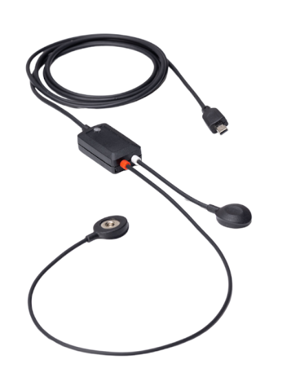
The EEG smart sensor is a research-grade single-leadsensor designed to acquire EEG (brain activity) signals through surface electrodes.
It features a low-noise differential amplifier with integrated hardware filtering, ensuring stable, high-fidelity recordings even in challenging experimental environments.
This article explains how to get started with the Electroencephalography (EEG) Sensor for Biosignals PRO.
Compatible Systems
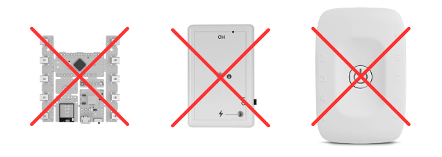
This sensor is exclusively compatible with Biosignals PRO systems.

This sensor is not compatible with any biosignalsplux or BITalino devices.
Recommended Setup
To complete this setup, you will need:
- 1x Biosignals PRO device
- 1x Electroencephalography (EEG) smart sensor
- Disposable surface electrodes
- Biosignals Studio (Desktop)
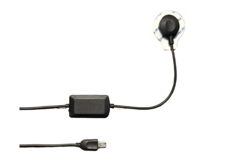
Connecting the Sensor to Your Biosignals PRO
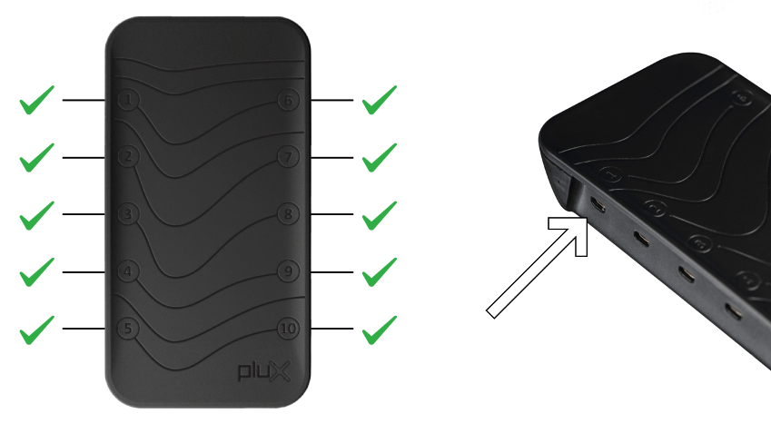
Connect the sensor to any of the available Biosignals PRO ports.
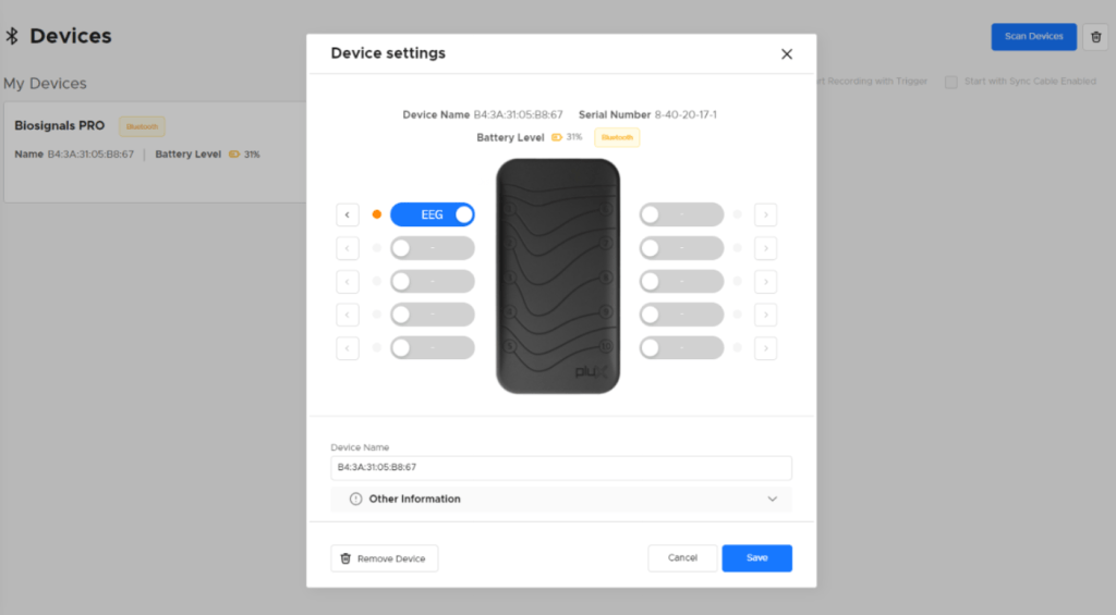
Once connected, the system will recognize the sensor, configure everything automatically, and activate it.
You can also see the sensor in the Biosignals Studio device settings, where it is listed as an EEG sensor on the connected port.
Placing Your Electrodes
The EEG Sensor for Biosignals PRO uses a differential input configuration with two active electrodes and one reference electrode.
For EEG acquisitions, electrodes are commonly placed according to the 10-20 system. The selected electrode positions should depend on the brain region and research protocol used for the acquisition.
Example electrode placement:
- Active electrode 1: FP1 — forehead
- Active electrode 2: FP2 — forehead
- Reference electrode: M1 — mastoid process, behind the ear
Note: This is only an example placement. Electrode placement should always follow the intended research protocol. The EEG Sensor for Biosignals PRO is intended for life sciences research and educational use only. It is not a medical device and is not intended for diagnosis, treatment, or clinical monitoring.
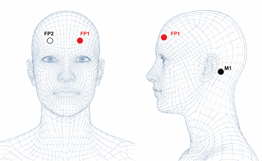
Electrode placement on the forehead Electrode placement of the reference electrode

For high-quality EEG recordings, we recommend:
- Prepare the skin: Follow the Skin Preparation Tutorial
- Use clean electrodes: Use new disposable electrodes or properly clean reusable electrodes before use
- Connect the electrode snaps from the sensor to the electrodes.
- Place the two active electrodes according to the intended EEG setup or research protocol, commonly based on the 10-20 system.
- Place the reference electrode on a stable location, such as the mastoid process behind the ear, or another reference position defined by your protocol.
- Choose electrode locations with minimal movement whenever possible to reduce motion artifacts.
Using a Reference Electrode
For EEG recordings, the reference electrode provides a stable reference point for the differential measurement between the active electrodes.
For best results, place the reference electrode:
- on clean, dry skin to ensure reliable electrode contact
- on a stable location with minimal movement
- in the reference location defined by the intended EEG setup or research protocol
- commonly on the mastoid process behind the ear, such as M1 or M2, when defined by or suitable for the protocol
Avoid placing the reference electrode on areas with poor contact, excessive movement, or locations that may interfere with the active electrode positions.
Note: The reference electrode position may affect the recorded EEG signal. Always choose the reference location according to the intended research protocol.
Before Starting the Acquisition
Before starting the acquisition, confirm that the electrodes are properly attached, the cables are stable, and the participant is comfortable and remains as still as possible.
Sensor Signals Interpretation & Samples
The EEG Smart Sensor should be automatically recognized by Biosignals PRO and listed in Biosignals Studio as an EEG sensor on the connected port.
During acquisition, you should be able to record the raw EEG signal. EEG signals are typically low-amplitude and may vary depending on electrode placement, participant state, and recording conditions.
A stable EEG recording should show a continuous waveform with relatively low noise under low-motion conditions. Short signal changes may occur during eye blinks, eye movements, facial muscle activity, or other movement-related artifacts.
You may also see the Motion Score, which indicates the intensity of movement affecting the sensor. Increased Motion Score values may indicate movement, electrode displacement, or other artifacts that can affect signal quality.
If the signal appears unstable, noisy, or saturated, check the electrode setup described above before starting or continuing the recording.
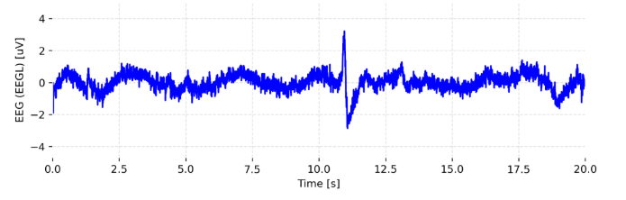
Raw EEG sensor output.
Motion Score
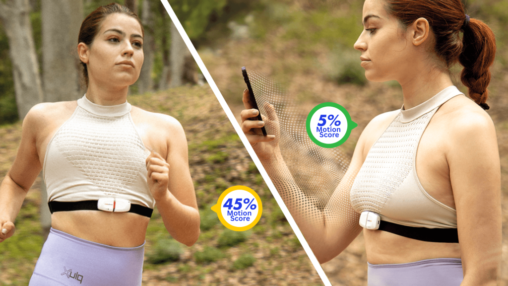
Motion Score is a computed metric available on all Biosignals PRO Smart Sensors.
It combines data from the sensor’s accelerometer and gyroscope to quantify motion intensity during a recording.
The resulting value is expressed as a percentage between 0% and 100% and provides an intuitive representation of the amount of movement. A higher Motion Score indicates more intense movement. For example:
- 0–10%: Rest or small involuntary movements (talking, coughing).
- 10–20%: Walking, spinning, or sleep-related movements.
- 20–40%: Fast-paced walking or jumping.
- 40–60%: Jogging or running.
- 60–80%: Fast running.
- 80–100%: Explosive movements with rapid deceleration (e.g., tennis strokes, punching).

This makes Motion Score useful for:
- Detecting movement artifacts that may affect other sensor readings (e.g., EMG, ECG).
- Assessing motion levels in a simplified way without needing to process raw IMU data.
- Comparing activity between different sensors placed across the body (e.g., arm vs chest).
Find out more details about the motion score here:
